This project has been on my mind for a few years now, and has been a long time coming. If you know me, you could probably just guess the amount of shit that I have saved up on my desktop and servers. In my main desktop system I have several drives consisting of 40gb, 40gb, 80gb, 160gbRAID (2x80gb), DVDRW. This is all well and good, however to show off my collection of drives I have a single red led on the front which is almost always on. Sorta weak.
I was reading around on google about what IDE cable wires do, and I was drawn to pin 39, “Activity”. Further searching revealed that there has been a few attempts to use that pin. Zapwizard had a good how to on this, which I followed, and it sorta worked. I did in fact get activity displayed on LED, however my system would fail boot up if I didn’t have the wires of the IDE cable tied together. Once started up, I could pull the wires apart and it would work fine.
I had to think about this a bit to try and figure out what was making the boot up fail, and as I later found, pin 39 informs the motherboard of the order of the drives, not only in cable select modes, but in specified as well. Pin 39 is usually floating, but activity signals out by grounding the pin. I checked continuity between the Primary and Secondary sockets’s pin 39, and found that they aren’t talking to each other, but when either is grounded, the LED on the front cover would go on. I eventually came to the idea of using Diodes to isolate the voltage drop between the two drives, while still maintaining proper communication to the motherboard from each drive. Success!
NOTE: Neither Coreforge.com, myself, or anyone involved with using this information can be blamed for you screwing up and doing any harm to yourself or your system. This probably voids some warranty. Be warned.
How I hooked it all together:
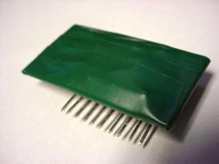
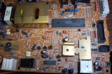
The virgin sacrifice.
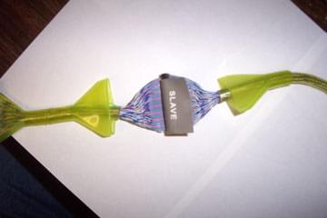
Easily pulled the hoods off with some twisting.
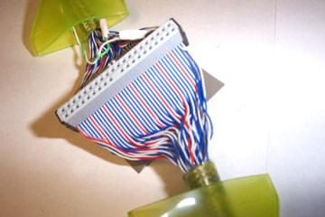
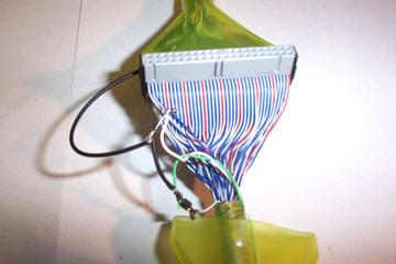
Since this is an 80 conductor, every other
wire is ground. I used wire 78 (3rd to last).
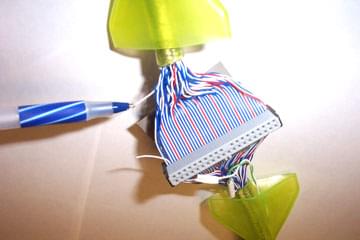
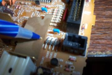
Found the lead going to the motherboard. If you have a
continuity tester, check to see that it isn’t just a ground wire.
Let the end facing the slave adapter hang, its not needed.
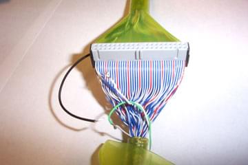
The black lead is the MB lead run to this side for wiring.
I have already soldered wires to the master and slave wires.
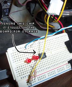
I needed some diodes, and I’m cheap, so I stole
them from a junked laser printer sitting around.
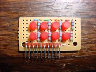
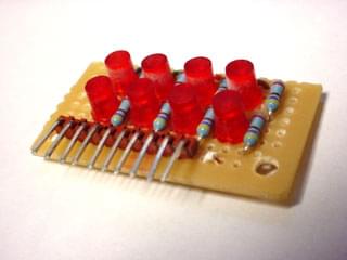
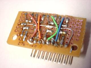
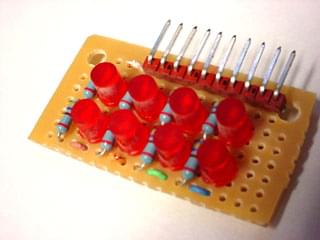
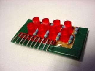
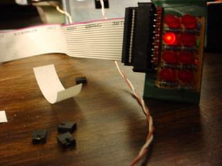
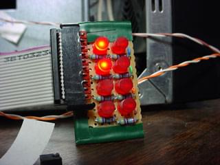
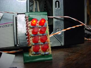
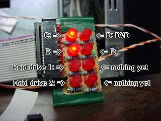
Very pleased with the results, I decided that I should make a finalized version of the display. I have 6 devices hooked up to my IDE cables, but why not add a little more? So, without further ado, here’s what I ended up making: