When working with battery powered devices, knowing how much power they consume will tell you how long they will last on a charge or a fresh battery. This is imporant to know when replacing the stock firmware with ESPHome or Tasmota, which can drastically change the power consumption of the device. Many battery-powered IOT devices spend the majority of their time in a deep sleep state, and only wake up briefly to perform a task, then go back to sleep. This is great for battery life, but makes it difficult to measure the power consumption of the device over time. The INA219 is a great little chip that can measure both voltage and current, and when paired with a microcontroller, can be used to measure the power consumption of a device. This post will cover how to use the INA219 with ESPHome to monitor the power consumption of a device.
I had initially thought I was going to be starting from scratch, but I found a great project video by GreatScott! on YouTube, covering his solution for monitoring power, using the INA219, an ATMega328p, and an SD Card. This was great motivation to get things ordered and begin building, but after using it a few times on a breadboard, I found it clunky to have to pull the SD card out and read the data on a computer. I wanted something that I could access at any time during the process, without interrupting the device under test. Additonally, I had a number of times in testing where I needed to A/B test different things, requiring me to swap things out and retest each time. If the test lasts a long duration, this can be a real pain. As a second requirement of my redesign, I wanted to have two INA219s, so I could monitor two things in parallel.
These changes have several major benefits:
- Monitoring two things at once without swapping things out halfs the test duration.
- Monitirong two things at once allows me to perform identical behavior on two devices, and compare the results. Triggering a sensor, changing temperature, etc. There is no guesswork or notes involved, like “run for 5 minutes, then trigger door-open twice, then deep-sleep, then repeat”.
- Monitoring the devices under test in real time allows me to abort the test if there is a problem, or if I need to make a change.
- I don’t have to worry about SD card capacity or corruption.
Since I don’t want to log to an SD Card, and because I’ve been working with ESPHome a lot recently, thought I’d use it to log the data into MQTT or Home Assistant using an ESP8266. Fortunately, I found that someone had already done most of what I’m looking for, and was able to achieve it using plain ESPHome YAML, amazing! EasyPower by ohdarling is a great project, except that it only supports one INA219. Since their project is just ESPHome YAML, it looks like it would be easy to modify it to support a second INA219… more on this later.
Hardware
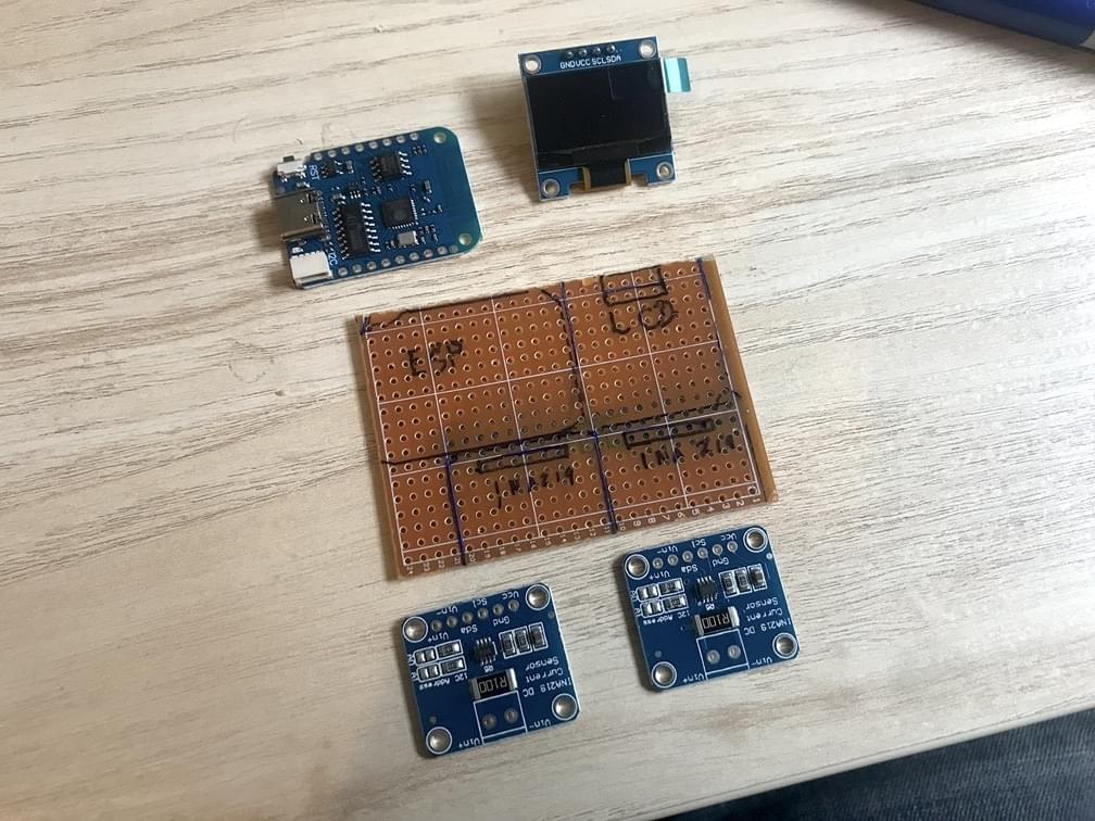
Since I have a total backlog of projects, and I don’t want to get caught up in yak-shaving, once I verified things to be working using a breadboard, I skipped the PCB design/etching and just threw something together on some stripboard, cobbling together our four modules:
- ESP8266 Wemos D1 Mini
- 128x64 OLED Display with I2C pins
- INA219 (x2)
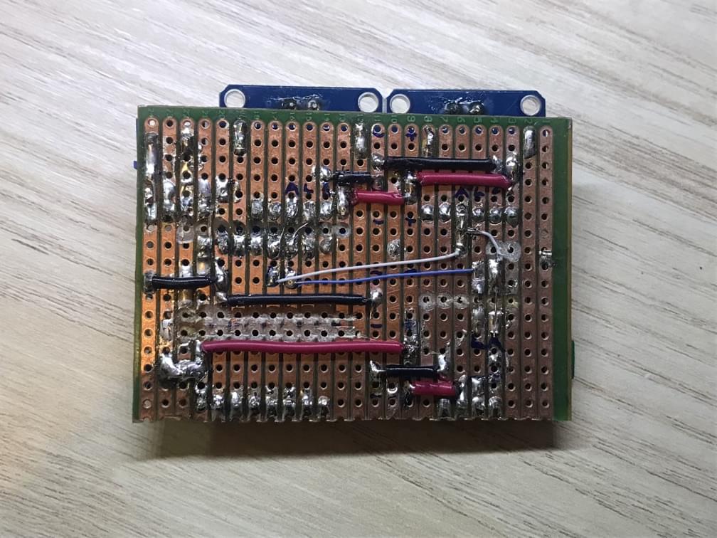
I hadn’t used stripboard in a while, and made a few errors along the way. If I had invested some more time into planning the layout, I could have made it a lot cleaner, and made more use of the copper traces on the back of the board, and fewer bodge wires. At least everything looks nice from the front.
One thing which kept escaping me in examples of the INA219 was the weird floating voltage, or inconsistent grounding between people’s projects. I found that grounding the INA219 to the device under test is necessary to actually get valid readings. Also, it wasn’t clear if the same voltage that powered the device under test should be used to power the INA219. I found that it didn’t matter, as long as the device was grounded to the INA219 GND. Because of these findings, I wanted the option to supply power the device under test from the test rig, or let the device use it’s own power supply. To do this, I added a screw terminal with a GND, and a voltage output. The voltage output can be set to 3.3V or 5V using a jumper. The source of 3.3V is currently being supplied by the Wemos D1 Mini, but I may change this to a dedicated regulator in the future.
Since we are using two INA219s, we need to change the I2C address of one of them. This is done by connecting the A0 pin to GND, which is done by shorting one of the address pads on the module itself. This will set the two INA219s to 0x40 and 0x41.
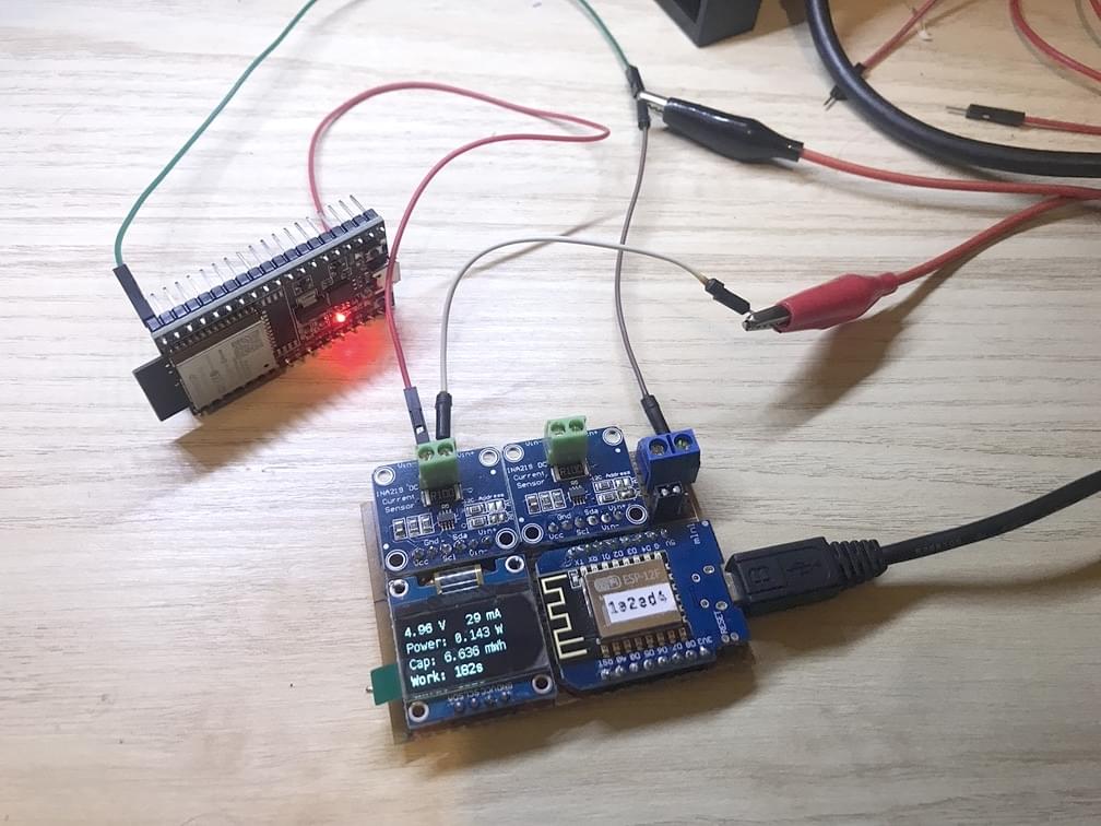
The photo above shows a device under it’s own power, with the load positive flowing through the INA219, and a jumper wire connecting the device’s GND to the INA219 GND.
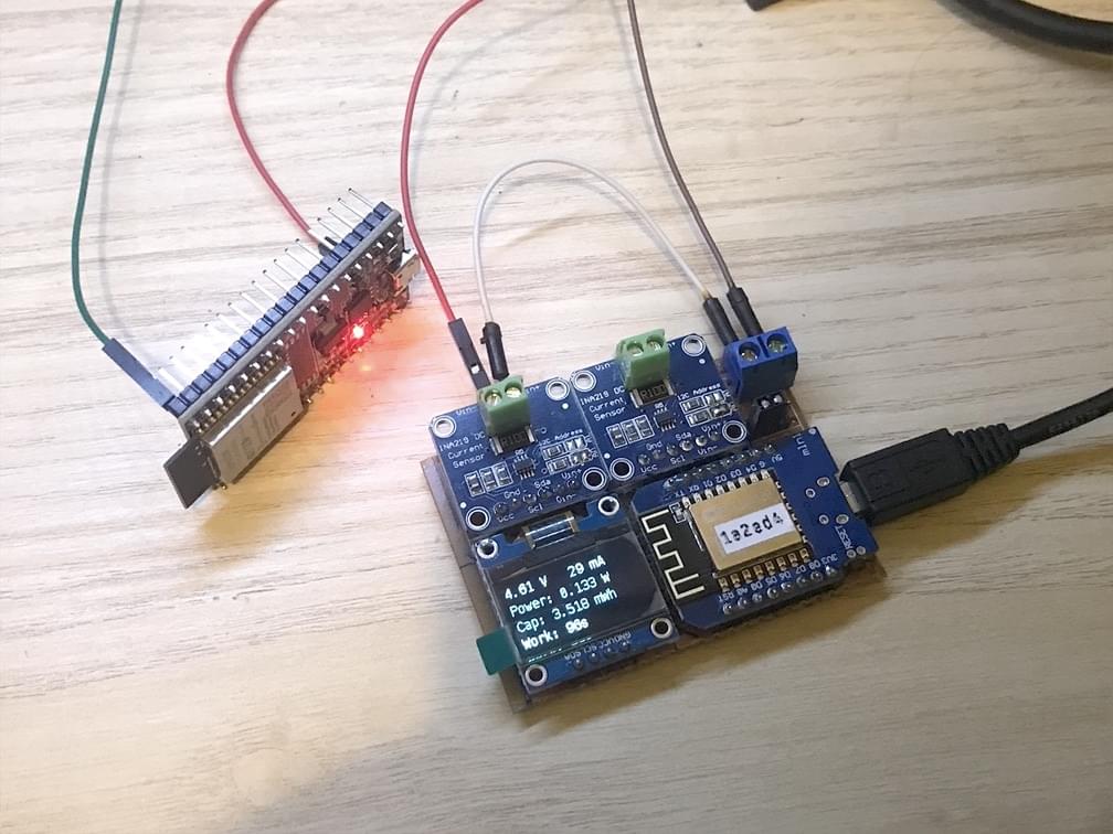
This photo shows the same device, but powered by the test rig. There is a white jumper wire connecting the test board 5V to the INA219 Vin+, and the device is being powered by INA219 Vin- and the GND terminal.
A little bit of a mess, but it works.
Software
The YAML changes sounded pretty simple, being a modified version of the EasyPower project, however I’m running into some issues. It seems that the ESPHome INA219 sensor component doesn’t support renaming the sensor, so while I can configure two INA219s, I can’t tell them apart in MQTT. I’m going to leave the second INA219 out of the YAML for now, and just use the first one. I’ll update this post when I figure out how to get the second INA219 to work. Hopefully, there is something in config that I’m missing, but worst case, I’ll have to fork ESPHome in order to edit the source, allowing to let me rename the sensor.
1 | # ... general ESPHome config ... |
Ref: