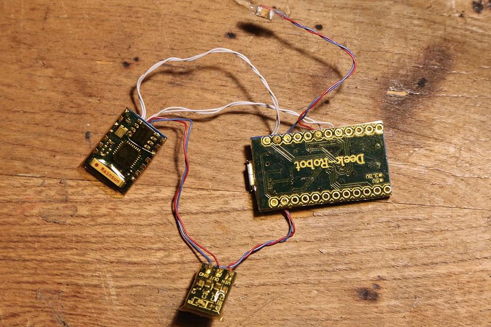
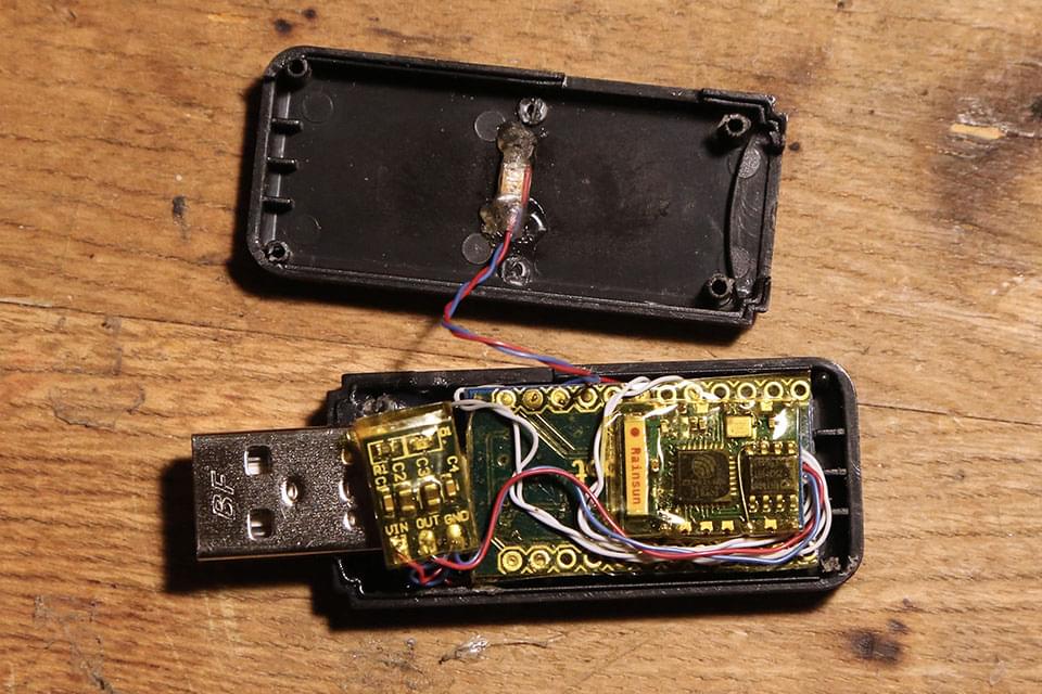
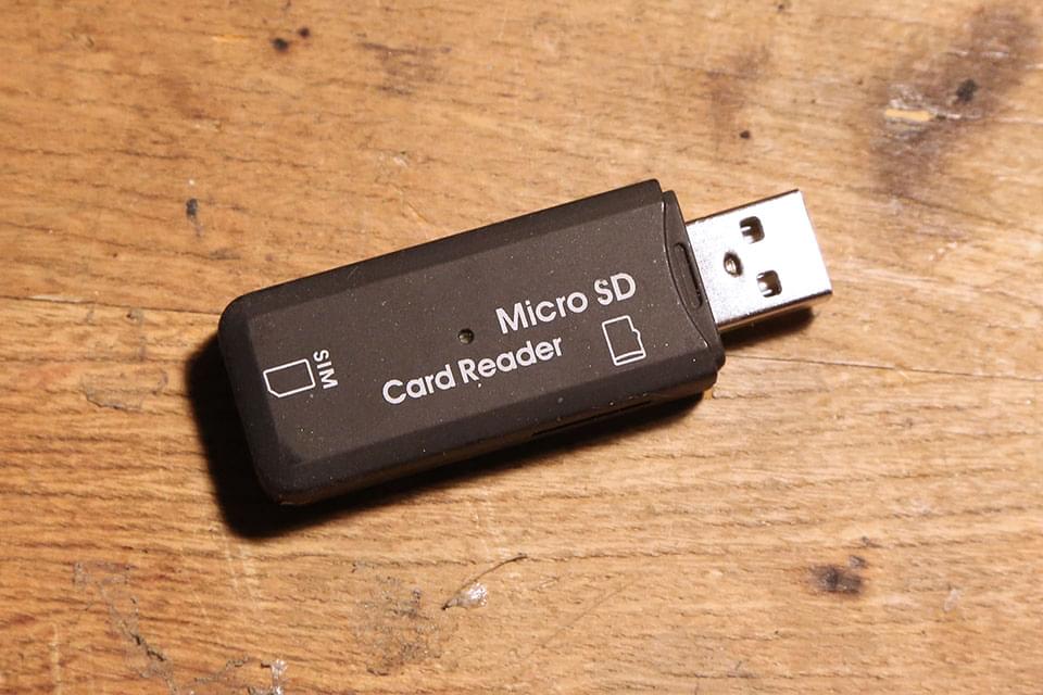
The good folks over at Hak5 have created some really cool penetration testing hardware, my favorite being the USB Rubber Ducky. “The USB Rubber Ducky is a keystroke injection tool disguised as a generic flash drive.” It’s a very flexible, awesome tool in a small, unsuspecting package. I don’t actually own one of these devices, but to me, it fell under the category of “I bet it would be fun to build something like that for myself”.
I came across a couple of great projects on GitHub where they emulate the functionality using an Arduino Leonardo/USB Pro Micro or using a Digispark, both of which I had a few floating around. One Github project that really caught my eye was Wi-Fi Ducky by spacehun. He paired an Arduino USB Pro Micro and an ESP-12 to create a WiFi-enabled USB Rubber Ducky, allowing you to pick payloads and edit your scripts wirelessly. I burned his code to both my Arduino and ESP and wired things up, and sure enough, things mostly worked. There were odd data corruptions, random pauses, stacktrace crashes, etc. In looking at the open issues, it looks like I’m not alone. The project hasn’t seen much work recently, so I took it upon myself to get things back on track. Others had added some features, but no one seemed to address the inconsistent communication between the two modules. I forked the project, brought together the best changes I could find from other forks of the project (with credit of course), and resolved most of the major nagging bugs I found in the project. I’ve have a pull request open to the main project, but until then, see my fork at https://github.com/Brayyy/wifi_ducky.
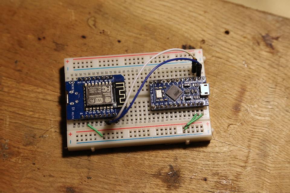
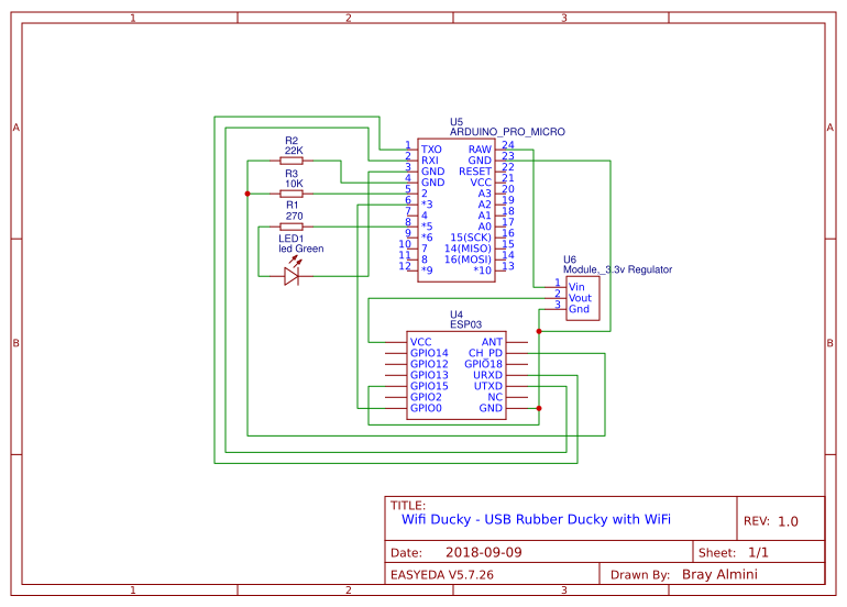
I tested most things out on the breadboard first, I could have hardwired ESP PD to VCC and let GPIO-0 float, but I wanted to leave the option to update the firmware over serial, via the Arduino, though I have yet to get this to properly work. Letting the Arduino switch GPIO-0 is easy, I just set it as output and LOW, but setting the ESP PD pin to 3.3v is a little more complicated, as the Arduino runs 5v. To get around this, I set up a voltage divider using 10K and 22K resistors between D2 and GND. Currently, the Arduino just sets GPIO-0 LOW and PD HIGH on startup. If I want to put the ESP into programming mode, I have to pull GPIO-0 LOW, and toggle PD, and currently clamp straight to TX/RX, not programming through the Arduino.
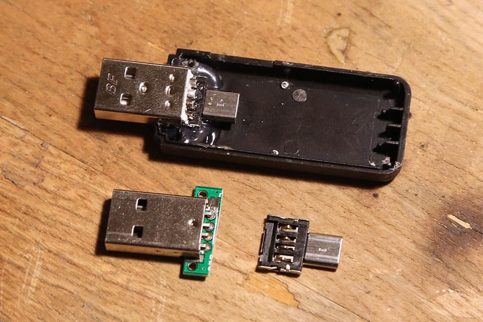
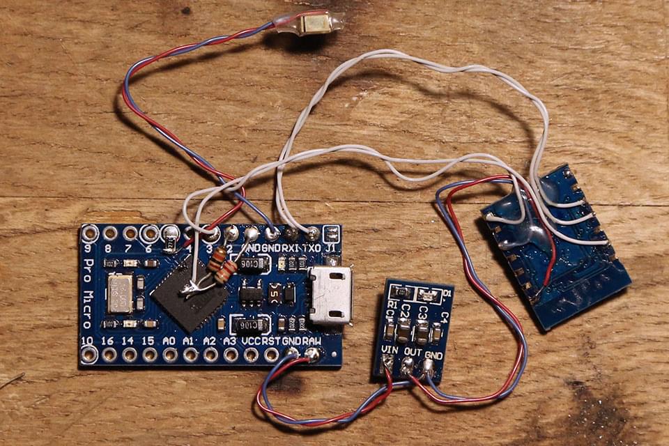
For the connector and USB package, I drew inspiration from behindthesciences.com, creating this extremely short USB-A to micro USB male “cable”. Initially, I was going to solder USB lines straight to the Arduino, but going this route allows me to tear things apart and reuse the main components if I decide to later. This also allows me to work on the guts, verifying that everything works before cramming it all into the case.
Links I found useful:
