I recently picked up a couple of no-name WiFi switch from AliExpress, they are sold under a variety of names, but the ones that look like mine all use the Tuya app. I was hoping to flash it with ESPHome, but unfortunately, it doesn’t contain an ESP8266 module, instaed using a Tuya CB3S module, which is not supported by ESPHome. These switches had been using ESP-12F modules for some time, but have since transitioned to CB3S. Fortunately, I was able to find a project called OpenBeken, which is a custom firmware for the Tuya CB3S module. It’s more basic than ESPHome, but it did actually do what it said it would, with very little effort.
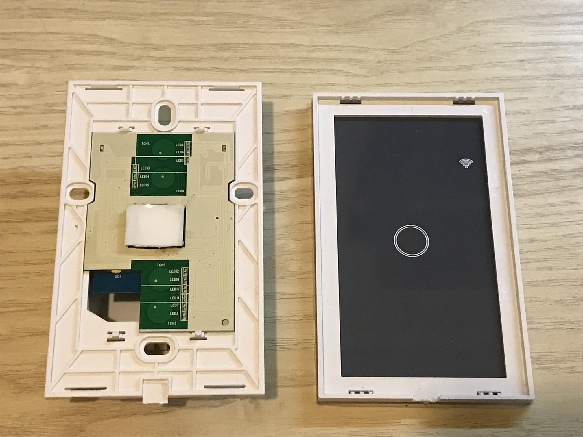
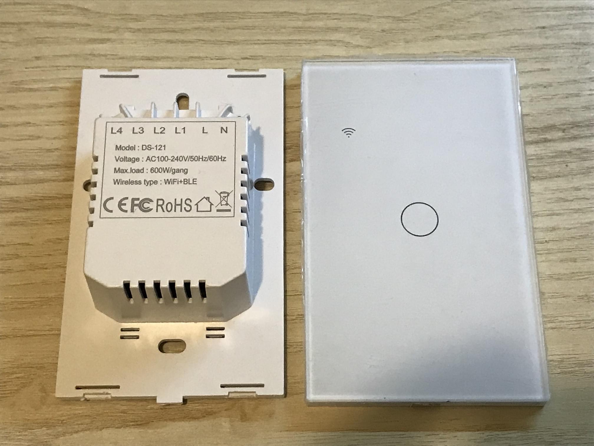
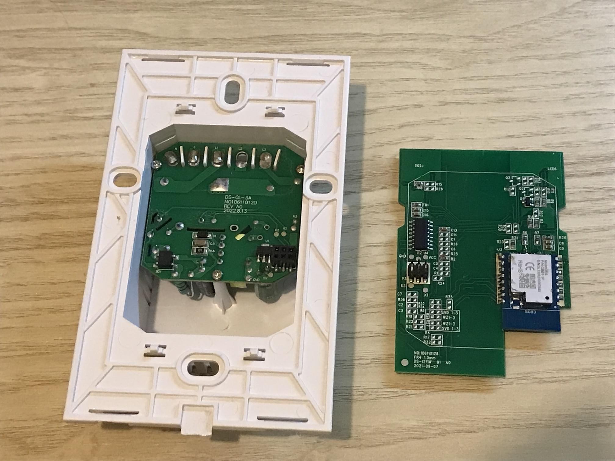
Disassembly
Flashing and mistakes
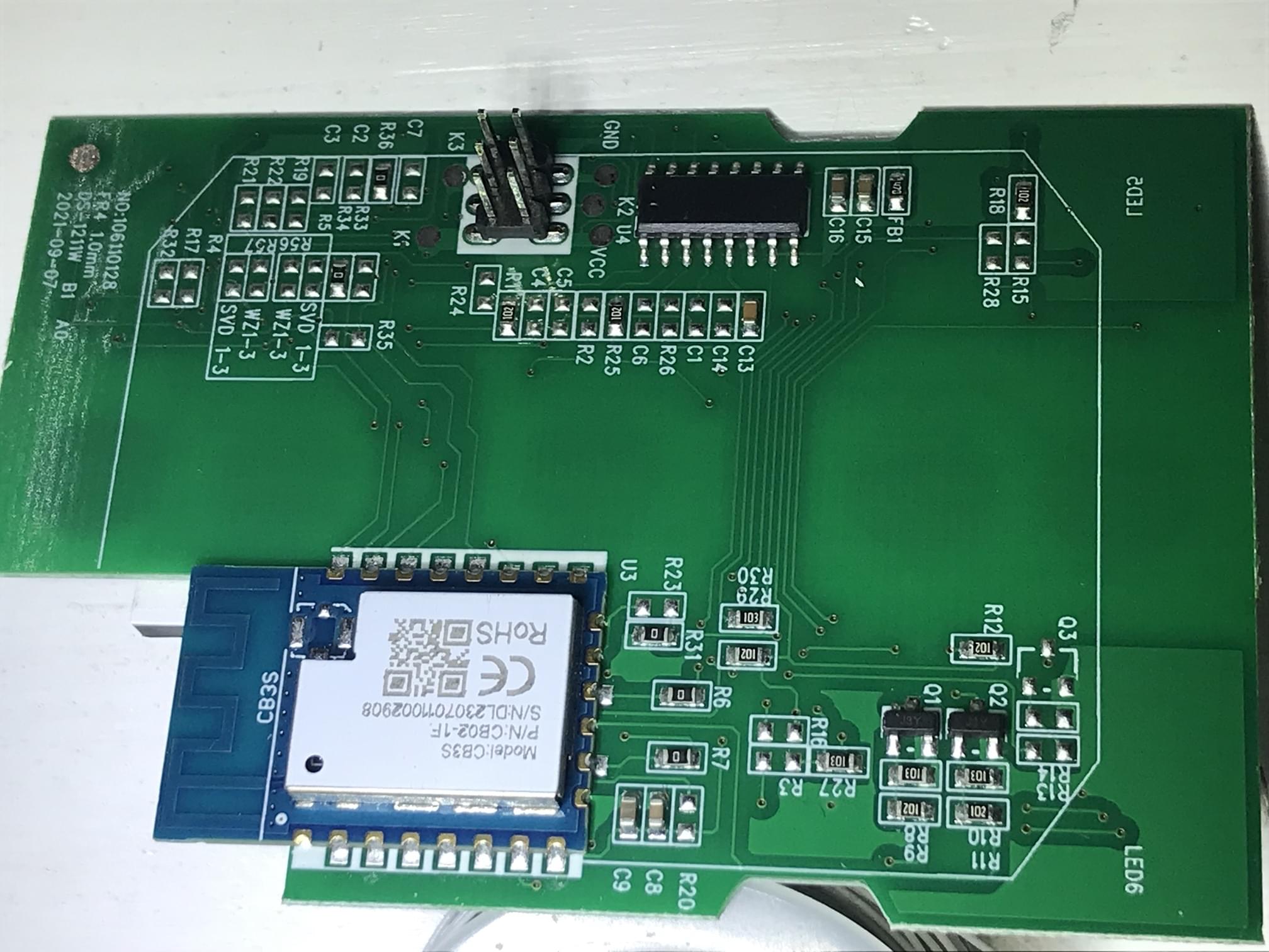
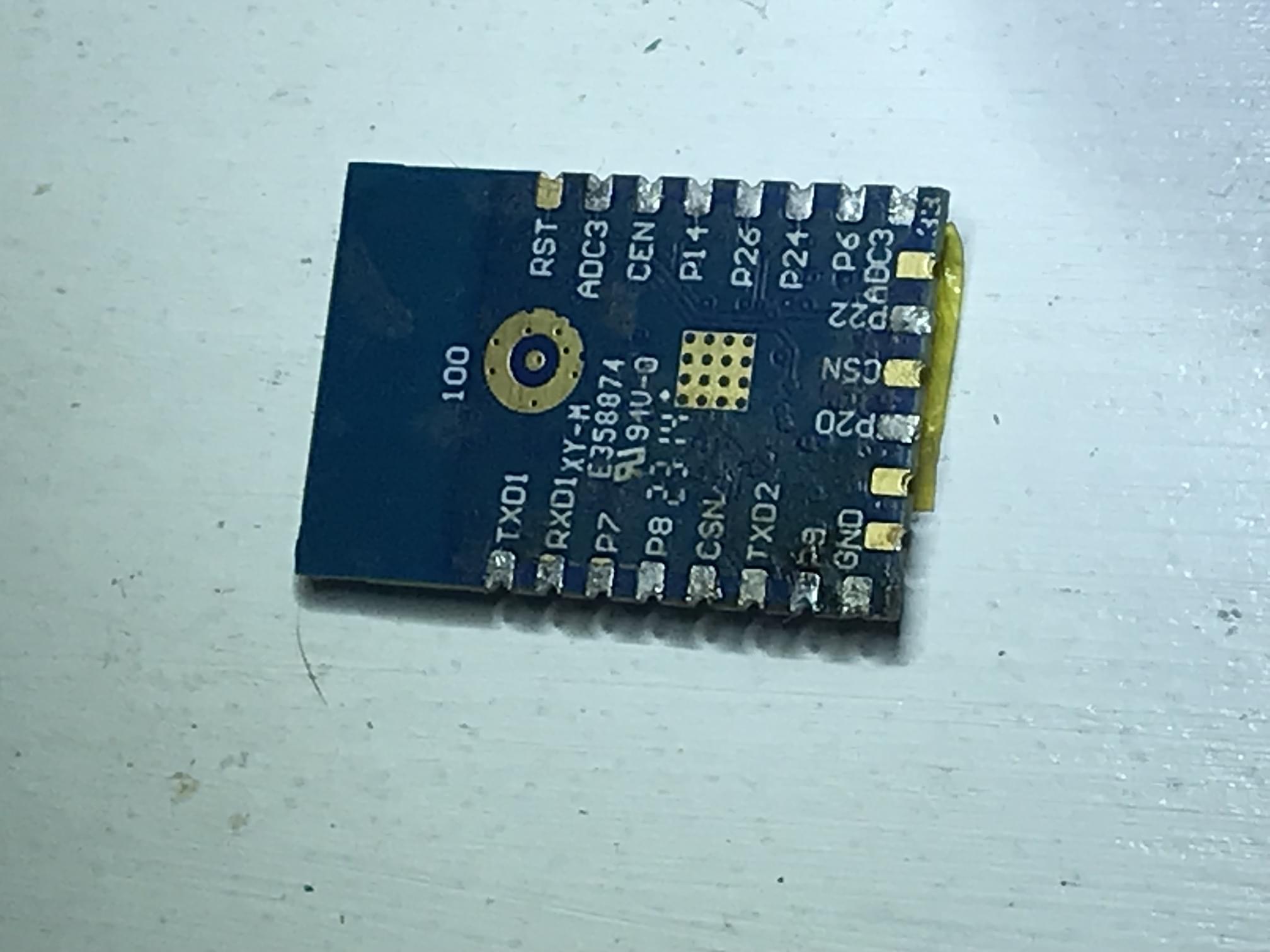
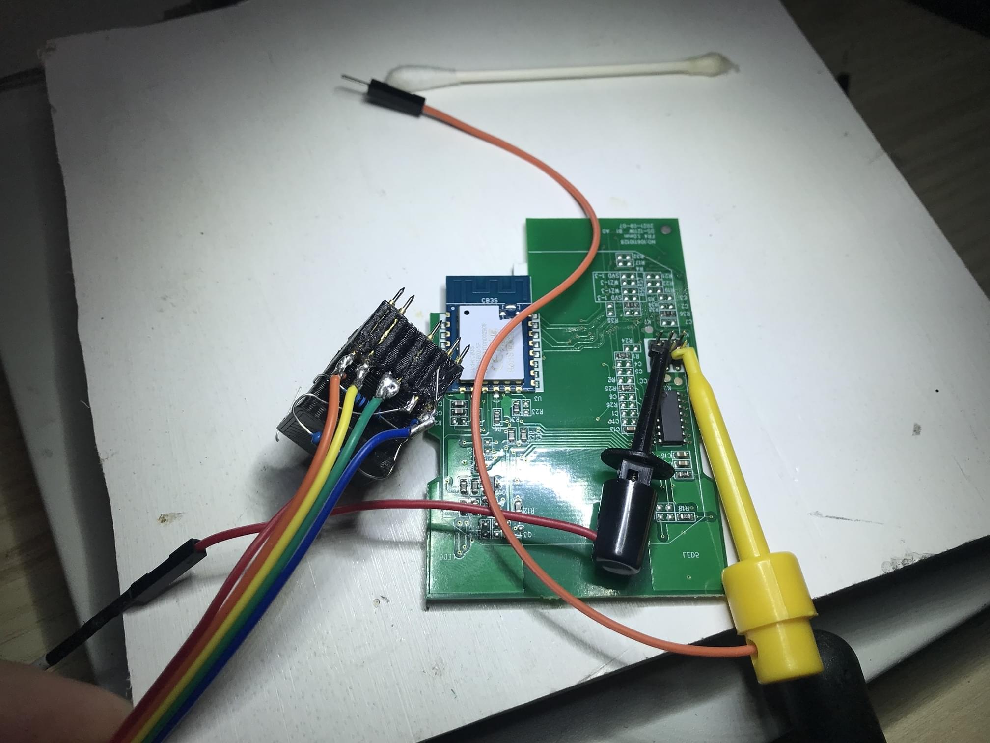
Initially, I had assumed that the Wifi module was an ESP-12F, and there were problems programming it while installed in the switch. I removed the chip from the board, but still had issues, only later finding out that Tuya (or whomever) had switched to the CB3S module. While the two modules are generally pin-compatible, they take very different firmware, and the CB3S module is not supported by ESPHome or esptool.py.
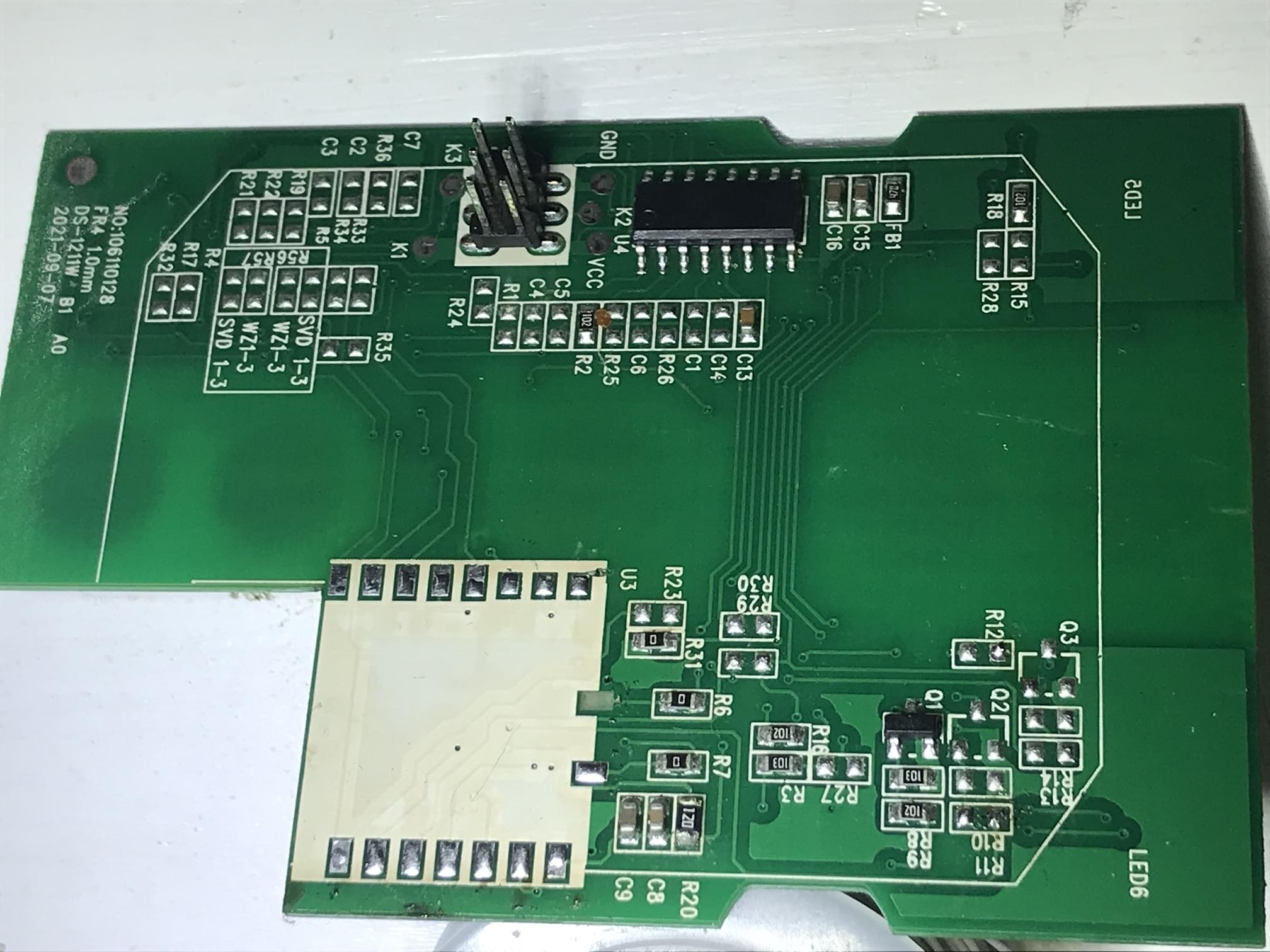
I then decided to replace the CB3S module with an ESP-12F module, but I was unable to get the ESP-12F module to work once soldered to the board. I suspect that there was at least one GPIO pin in a low or high state that prevented the ESP from booting. Before going too far down the debug hole, I came across several projects which had claimed to have successfully flashed the CB3S module, and decided to give that a try.
After a lot of failed attempts, I discovered OpenBeken, which conveniently has a pre-built firmware images on their releases page. In their documentation, I came across a tool called hid_download_py, which performs similarly to esptool.py allowinng me to flash the firmware over FTDI serial.
Update 2023-12-21:
Don’t use
hid_download_py/uartprogram, it’s too low-level and can easily mess up the bootloader. Use ltchiptool instead, read the blog post here: Almost bricking BK7231N modules
1 | # Backup existing firmware three times to ensure we have a good copy |
Configuration
The OpenBeken firmware is fairly straightforward. It has a web interface for configuration, and supports MQTT. On initial start up, it will create a WiFi access point, which you can connect to and configure the device. Once configured, it will connect to your WiFi network, and you can access the web interface at the IP address it was assigned by your DHCP server. I also enabled MQTT, and configured it to connect to my local Mosquitto broker.
Once it was happily running on my network, it was up to me to prod all of the GPIO for their function. Luckily, the OpenBeken firmware has a built-in GPIO tester, which allows you to toggle each GPIO, and see the results on the board. Once you figure out all of the GPIO output, you can prod for the GPIO input, and figure out which GPIO is connected to the button.
OpenBeken has an interesting way to quickly configure devices using pins, roles, and channels. Channels link roles together, for instnace if you have GPIO for a switch, a relay, and a status light, if all of these are on the same channel, it’s assume they all work together.
For my use case, I have two switches, one has a single relay/switch/light and the other has two.
Single-gang switch:
| GPIO | Role | Channel |
|---|---|---|
| P6 (PWM0) | Rel | 1 |
| P20 (N/A) | Btn | 1 |
| P22 (N/A) | WifiLED | |
| P26 (PWM5) | Led | 1 |
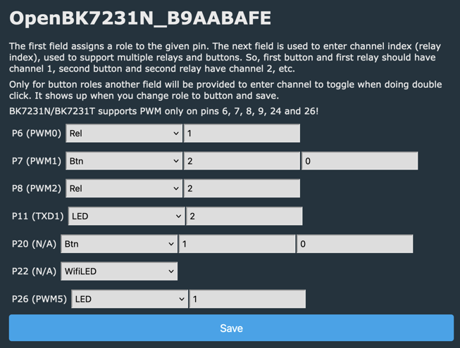
Double-gang switch:
| GPIO | Role | Channel |
|---|---|---|
| P6 (PWM0) | Rel | 1 |
| P7 (PWM1) | Btn | 2 |
| P8 (PWM2) | Rel | 2 |
| P11 (TXD1) | Led | 2 |
| P20 (N/A) | Btn | 1 |
| P22 (N/A) | WifiLED | |
| P26 (PWM5) | Led | 1 |
The switches now properly work when physically pressed, and I can control them via MQTT.
I can read and states in MQTT using the following topics:
1 | # Switch 1 |
I setup up the following Home Assistant configuration to control the switches:
1 | mqtt: |